-
Download Logisim For Mac카테고리 없음 2020. 2. 11. 19:45
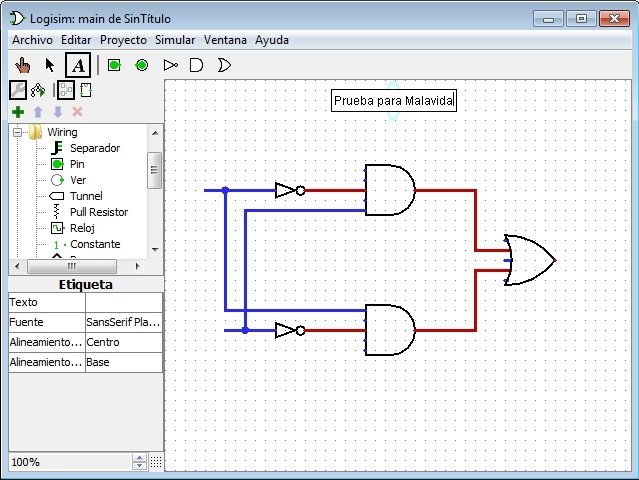
CS120 - S15 Lab 04 Intro to Logisim CS-120 Summer 2015 Lab04 Introduction to Logisim Overview Logisim is a transistor/gate level circuit design tool and logic simulator that makes it easy to create circuit schematics and test them to make sure they work correctly. Logisim is written in Java, and will run anywhere Java runs (e.g.
- Logisim 2.7.1 An educational tool for designing and simulating digital logic circuits, featuring a simple-to-learn interface, hierarchical circuits, wire bundles, a - Soft-Download.
- Speed Download Lite. Overhauled from top to bottom, Speed Download Lite is a stripped. Version of the Speed Download 5 download manager - without any of. And browser integration, Speed Download Lite offer the same.
Unix, Windows, MacOS. Pretty much anywhere).
There are virtually no differences using Logisim on any of the platforms, so install Logisim on your own computer, and use it for labs and study, or use the LDAP machines in the lab. Either one or both is OK. Installing Logisim Software on the LDAP Computers in the Lab Before we can do anything meaningful with Logisim, we need to download and install Logisim software from the web. In order to do this, follow the following procedure. Here's a link to my web page.). Go to web site in your web browser. Click on the logisim-generic-2.7.1.jar hyperlink.
Free download page for Project Logisim's logisim-macosx-2.7.1.tar.gz.An educational tool for designing and simulating digital logic circuits, featuring a simple-to-learn interface, hierarchical circuits, wire bundles, and a large component library.
(If you are running Chrome, you will get informed that this kind of file could harm your computer. If you get that message, say 'Yes' to download anyway.) If you want to download on your laptop, there are self-install options for both Windows and Mac-OS which make installation even easier, but you will need to install Java if it is not already on your laptop. If you install on your laptop, skip the rest of these directions, and go straight to. Open a terminal window. List the contents of your Downloads directory to make sure you got the file. Do this by typing ls Downloads.
You should see a file called logisim-generic-2.7.1.jar in the list of files reported by ls. If not, check with the teacher. Create a new sub-directory from your home directory called 'logisim' by typing mkdir logisim. Move the jar file you downloaded from the Downloads subdirectory to the logisim subdirectory you just created by typing mv Downloads/logisim-generic-2.7.1.jar logisim. Change to the logisim directory by typing cd logisim.

Create a logisim command gedit logisim& This will open a gedit window on a blank file. In the gedit window, type java -jar./logisim-generic-2.7.1.jar&, and then save the file.
Back on the terminal window, make the logisim file 'executable' by typing chmod +x logisim. Test out your installation by typing./logisim in the terminal window (don't forget the dot slash in front.) If you did everything right, the Logisim main window should come up on your screen.
If anyone is interested, you can create an icon for Logisim to run from the 'Activities' window. From the Activities menu, choose Applications/System Tools/Main Menu. In the screen that comes up, select Education (since this is an educational tool). Click on the New Item button.
This will open up the Create Launcher window. In the Create Launcher window, type Logisim in the Name field. Click the Browse button to the right of the Command field. This will open the Choose an application. In that window, click on the folder with your user ID to get to your home directory. Then double click on the logisim folder you just created, and then click on the logisim file to select it, and click on the Open button.
Then click on the OK button on the Create Launcher window. Then click on the Close button on the Main Menu window. If everything is correct, now you should be able to go to Activities/Applications/Education and click on the Logisim icon and have Logisim come up. Start Logisim if it is not already running. On the Logisim main menu, choose Help and then Tutorial. Go through the process of creating an XOR circuit and testing it, as outlined in the tutorial.
Once you have gone through the tutorial, browse through the Libraries and attributes and Sub circuits sections of the Users's Guide. Feel free to explore more, but that's all you'll need for today. Once you're done, either close and re-open Logisim, or choose Edit/Select All followed by the delete key to reset your circuit to empty. Creating an Adder Create a Half Adder Sub-Circuit As part of the homework due June 9, we created truth tables for binary addition. Asked for a truth table for the sum of two bits.
The answer was as follows: A0 B0 S 0 0 0 0 1 1 1 0 1 1 1 0 Part b. Of the question was a truth table for the carry bit from the same addition, as follows. A0 B0 CO 0 0 0 0 1 0 1 0 0 1 1 1 The first step to making a complete adder is to make a circuit that implements these two truth tables.
Download Logisim For Windows
Start in an empty Logisim file, and choose Project / Add Circuit. Then type in halfadder to name the circuit you are about to create. Now create input pins A0 and B0, and output pins S and CO and the gates required to implement the truth tables above. Test your circuit by putting different values of 1 and 0 on the input pins and make sure the output pins have the correct results. Create a Full Adder Sub-Circuit The half adder takes care of the first column of a binary addition, but the rest of the columns have more complicated logic because you have to account for the carry in bit from the previous column.
Remember from the homework the truth tables for all the other columns are as follows: A B CI S CO 0 0 0 0 0 0 0 1 1 0 0 1 0 1 0 0 1 1 0 1 1 0 0 1 0 1 0 1 0 1 1 1 0 0 1 1 1 1 1 1 Create another sub-circuit called fulladder which has input pins A, B, and CI, an output pins S and CO that implements the truth tables for a full adder. In Logisim, the behavior of a 3 input XOR is controlled by an attribute on the XOR gate. By default, Logisim treats an XOR as true 'When one input is on'. This doesn't match what I've taught in class, and is not the typical interpretation of a 3 input XOR gate. To change this behavior, with the XOR selected, go to the attribute list, and find Multiple-Input Behavior. If you left click on 'When one input is on', you will get a pop-up that allows you to select between 'When one input is on' and 'When an odd number are on'.

Select When an odd number are on to get the standard behavior of an XOR. Creating a Mult-Bit Adder Circuit The goal of this lab is to create a 4 bit two's complement adder. In the upper left selection box of Logisim, underneath the icons, there is a list of circuits in this Logisim file, which should contain 'main', 'halfadder', and 'fulladder'. Double click on 'main', and you should get an empty schematic, and there should be a magnifying glass icon on top of the icon to the left of 'main'. Create input pins labeled A3, A2, A1, A0, and B3, B2, B1, and B0. Then create output pins labeled S3, S2, S1, and S0. Next left click on the 'halfadder' circuit, move to the schematic, and place the half adder in your main schematic.
If you move your cursor over the left side of the half-adder, you will get pop-ups that show you where the A0 and B0 connections are. Hook up the A0 and B0 pins to these. On the right side of the half adder, you can find red output connections for S and CO.
Hook up the S pin to the S0 output pin. Test your circuit by putting different values on the A0 and B0 input pins and making sure S0 has the correct values.
Now you are ready to add a full adder for the A1 + B1 column. Click on the fulladder row in the circuit selection, an place your full adder in the main schematic. Connect CO from the half-adder to CI of the full adder, and connect A1 to A, B1 to B, and S to S1. Try this circuit out. Do the same thing for the A2+B2 and A3+B3 columns. Finally, try various different values on the input pins, and look at the output pins. If you treat A3,A2,A1,A0 as a four bit binary number A, and B3,B2,B1,B0 as a binary number B, does your circuit produce S=S3,S2,S1,S0 = A+B?
What if you treat A, B, and S as a two's complement numbers? For extra credit, and one more output pin called 'Overflow' that is set to zero when the result in S is valid as a two's complement addition, but set to 1 when an overflow or underflow occurs. Create and wire the gates in the main circuit to detect an overflow.
When you are done, you might want to save your work in a Logisim file by doing a File/Save and specifying a name of your choice.
Publisher's description An educational tool for designing and simulating digital logic circuits, featuring a simple-to-learn interface, hierarchical circuits, wire bundles, and a large component library. As a Java application, it can run on many platforms. Features. Design circuits using an intuitive graphical interface. Watch the circuits be simulated as they are drawn. Runs under Linux, MacOS X, and Windows.
Build circuits from truth tables using combinational analysis module Available Translations: None.